In many electrical projects, engineer directly deals with measurements with few basic requirements like.
- High galvanic isolation
- Parameter display
- Direct communication with computer
- Data acquisition and storage with subsequent viewing or copying to the computer.
For Lowest Price I prefer to buy from Aliexpress .
Get the exclusive coupon hear
- Aliexpress Exclusive Coupon
- Bangood : coupon code [ 2020CNY ]
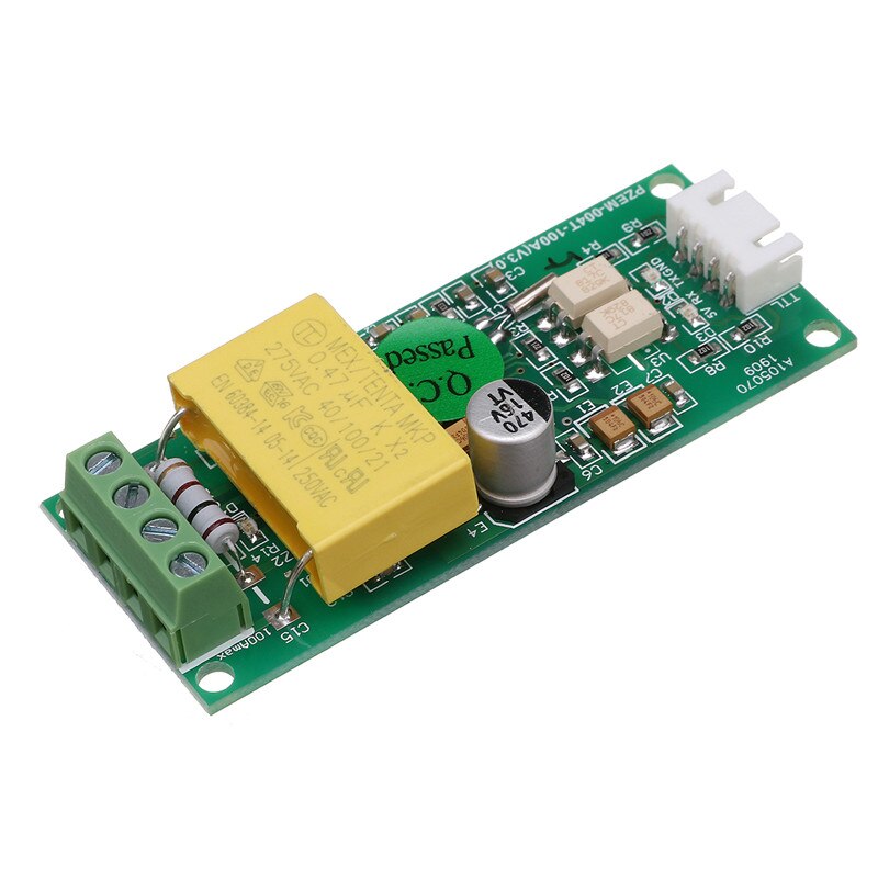
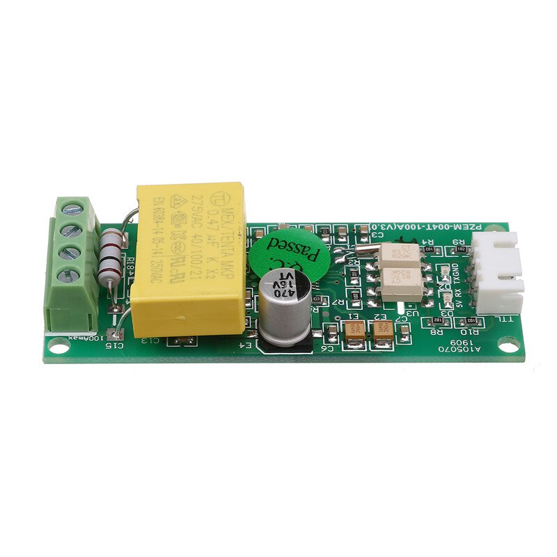
PZEM-004T V3.0 or Version 3.0 is the upgraded version to replace the old PZEM004T V1.0. The old version has been sold out in most of the online store and no produce anymore. The updated version of PZEM004T is best for the DIY project, where we need to measure the voltage, current, power, energy, frequency, Power factor (frequency and PF is extra added in the new version) using Arduino/ESP8266/Raspberry Pi like open-source platform.
Check price on Amazon.com | Aliexpress | Banggood | Amazon.in
This module comes with 3 different current measurement options
- 10A range with a built-in Shunt resistor
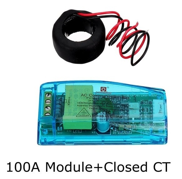
- 100A external closed Current Transformer
- 100A external split current Transformer
I recommend the shell protected split current transformer module for a project like Portable AC energy meter, Energy meter for electrical Lab, Energy auditing and measuring equipment etc. as split current Transformer is more flexible than closed one. Closed CT is a low-cost option suitable for fixed type projects like Residential Energy management system, Load control system, IoT based smart Energy meter, etc.
3. 100A external split current Transformer

The physical dimensions of the PZEM-004T v3 board is 3.01×7.3 cm, The pzem-004t V3 module is bundled with 33mm diameter 100A current transformer coil.
The new version has higher precision, faster refresh speed, and more stability communication than the old version.
Voltage
Power factor
Frequency
Current
Active power
Active Energy
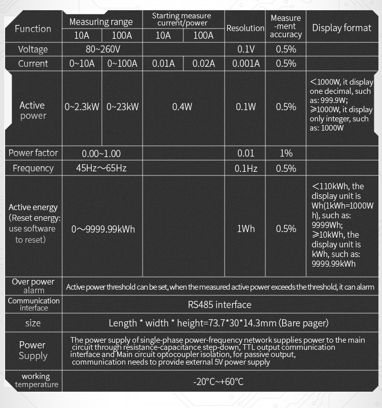
Function Description in short
Download links
Arduino PZEM004T V3 Interfacing
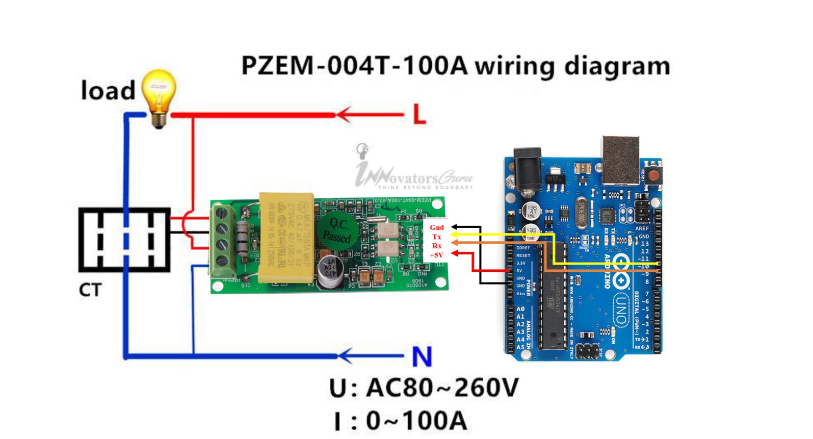
PZEM-004T V3 module has passive serial communication to connect Arduino Uno. Its RX and TX pin needs an external power supply. Connect the 5V pin to Arduino 5V pin, Rx pin to D11 of Arduino and Tx pin to D12 pin of Arduino, GND to GND. In the below diagram, PZEM004T V3 is connected to Arduino using Software serial. Use the following Program to test the module. Before compile download and install the PZEM-004T V3 library.
PZEM004T Arduino Code
This pzem004t Arduino code enable you to measure AC voltage, AC current, Power, Energy, Frequency and Power Factor on serial interface with arduino microcontroller. The library of PZEM-004t V30 works on hardware serial as well as software serial. The result of all parameters are printed on serial monitor of Arduino IDE. I tested this library code with arduino uno, arduino mega,and nano board.
NodeMCU/Wemos D1 PZEM004T V3 Connection Diagram
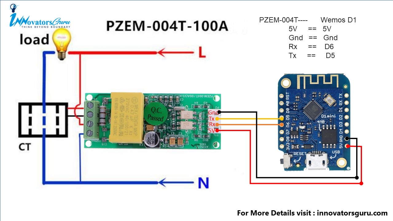
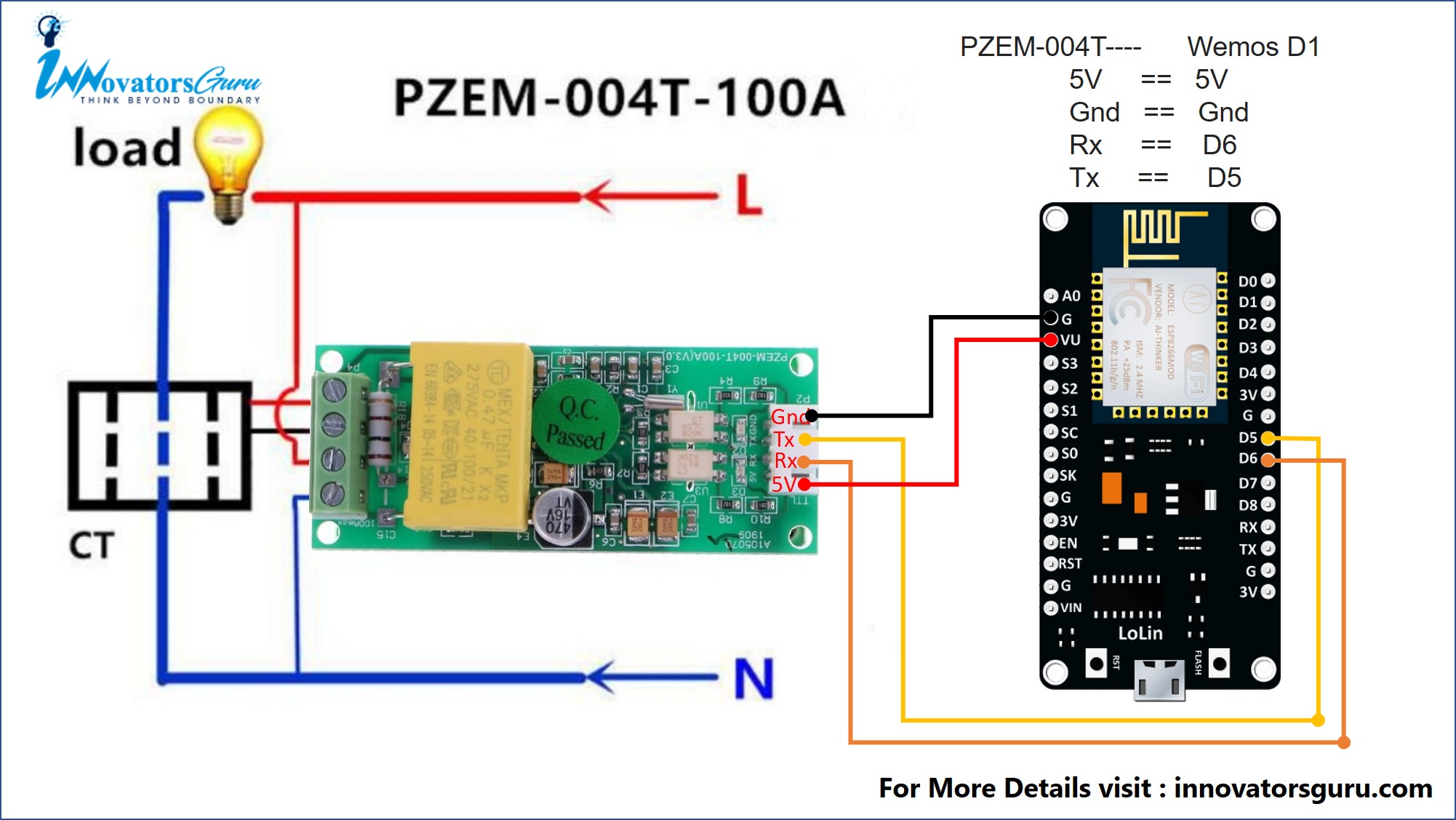
PZEM-004T V3 module serial communication to connect NodeMCU or Wemos. (Connection is same for ESP8266 NodeMCU) Its RX and TX communication pin needs external 5V power. Connect the 5V pin of Wemos D1 mini to PZEM004T 5V pin, Rx pin to D6 of arduino and Tx pin to D5 pin of Wemos, gnd to gnd. In the below diagram, we connect PZEM004T V3 to Wemos D1 Mini using Software serial. Use the program to test the module. Before compile, download and install the library.
Note: PZEM-004T V3 and ESP8266 NodeMCU are communication works on different voltage level theoretically but in practical life 3.3V nodemcu pins have tolerance of 5V. VU pin is USB 5V pin (only works when NodeMCU powered through USB)
PZEM-004T ESP8266 (NodeMCU) Code
This pzem-004t NodeMCU ( ESP8266 based development board ) code allows you to measure voltage, current, Kw, kwh, Frequency and PF display data on the Blynk app. The purpose of this code is to learn to connect PZEM-004T v3.0 to NodeMCU or Wemos Mini D1.
For complete code and explanations
Conclusion
As you can see, having a such low-cost module you can design best DIY Projects for your academics, Hobby or personal use etc. Remember to be safe while working on it as it comes with high voltage AC supply. As given in this guide, different projects will determine how you will use this energy meter module.
I hope you have found some useful tips in this article to carry out your electronics projects. I would love and appreciate your suggestions on how you feel we can improve this article upon. If you have gained a few tips from this article and it has helped you in any way, be generous to share it with others.
More Great Project Using PZEM-004T V3
-
AC Digital Multi function Smart Meter using Arduino and PZEM-004T
-
Smart Energy meter for Automatic Meter Reading (AMR) and theft Detection
-
PZEM-004T Alternative DIY AC Power Measurement using Arduino
-
IOT Based Energy Meter Reading Using Arduino
- fcgdam/PowerMeter: ESP8266 and PZEM-004T based Power Meter (github.com)
- ESP8266-PZEM004T : A WiFi enabled PowerMeter for AC energy monitoring. Simple and elegant Web-Interface implementations, a RESTful API, OpenHAB 1 & 2 Callbacks and a MQTT client.


Hello! This is my first visit to your blog! We are a team of volunteers and starting a new initiative
in a community in the same niche. Your blog provided us
valuable information to work on. You have done a outѕtɑnding job!
Hello! I could have sworn I’ve been to this blog before but after browsing through some of the post I realized it’s new to me. Anyways, I’m definitely happy I found it and I’ll be book-marking and checking back frequently!
As soon as I noticed this site I went on reddit to share some of the love with them.
Very interesting topic, regards for posting.
do this valid for all arduino IDE 1.8.10?
yes. its works.
I try the code and it didn’t work for me, here is the error message
exit status 1
stray ‘\342’ in program
I’m just a beginner so sorry if i’m make any mistake
[email protected]
first, check the connection of module and Arduino
Hello,
I receive error PZEMSoftwareSerial:2:24: error: invalid conversion from ‘int’ to ‘HardwareSerial*’ [-fpermissive]
PZEM004Tv30 pzem(11, 12);
^
In file included from E:\domotica\arduino-1.8.7\proyectos\PZEMSoftwareSerial\PZEMSoftwareSerial.ino:1:0:
E:\domotica\arduino-1.8.7\libraries\PZEM004T-master/PZEM004Tv30.h:65:5: note: initializing argument 1 of ‘PZEM004Tv30::PZEM004Tv30(HardwareSerial*, uint8_t)’
PZEM004Tv30(HardwareSerial* port, uint8_t addr=PZEM_DEFAULT_ADDR);
Can you help me?
So the accuracy only below 1%? Or the error only 1%?
it’s better to say error only 1%
Hello
I want to monitor an Ice making machine in real time. The ice machine uses Line1 and Line2 (each 120VAC), it does NOT use a ground.
So the machine is connected to only Line1 and Line2.
Can I connect the PZEM004Tv30 device to Line1 and Line2, instead of using Line1 and Neutral?
So basically I would have 240VAC across the AC input terminals of the PZEM004Tv30 device.
Please advise,
Thanks in advance.
mjd
Not tested for two-phase operation yet, As per my understanding parameters will affect as a sampling of the voltage and current signal will be done for n number of zero-crossing interval[ n : don’t know the exact value, may be 50 zero crossing as every reading comes after 1 sec (60Hz ) ].
when 2 different waveforms are combined resultant waveform across the sampling resistor will get affected. I think it does not work for the “line-to-line” voltage measurement.
Good day
Thanks for the fast reply:
OK, so the only issue connecting the PZEM004Tv30 device to Line1 and Line2 would be accuracy regarding the ‘sampling’ mechanism.
My concern is that the PZEM004Tv30 device will NOT burn up when connected to Line 1 and Line 2 .
If the Line to Line voltage is below the recommended 250VAC maximum, then overvoltage should not be an concern, it this correct?
Thanks in advance.
mjd
Resistor divider circuit is used for Voltage measurement mechanism, If the Line to Line voltage is below the recommended 250VAC it will not burn.
Hello
Thanks again for the fast reply:
OK, so I will use the PZEM004Tv30 device in his project and will report back with the results.
Should prove interesting.
Thanks and have a great day!
mjd
Sorry in above comment I meant to say ‘that it does NOT use a Neutral connection’ .
Thanks in advance.
mjd
Good day
I just downloaded the v9881D IC datasheet. http://www.ljdzsh.com/int/uploadpic/152782250820.pdf
Apparently the IC is setup for 50Hz grid conditions.
“V98XX is 50/60Hz-power-line supportive. By default the chip is applied for 50Hz-power-line. Users can
set the bit “PLLSEL” (“bit5” of “CtrlPLL”, 0x2868) to ‘1’ to configure the chip for the application in 60-Hz
power grid. The PLL clock frequency in 60-Hz power grid is 1.2 times of that in 50-Hz power grid. In 60-Hz
power grid, the parameters related to the clock frequency, such as the baud rate and timers, must be
reconfigured. ”
Of course this is ‘just’ the IC and not the PZEM004Tv30 device.
Have you tried the PZEM004Tv30 device on a 60Hz grid?
Or must all the registers be reconfigured as stated in the data sheet?
Thanks again.
mjd
what can i do to run these program on mega arduino 2560?
can you give me code ?
[email protected]
I’m just a beginner
We are adding code in the next morning to use pzem-004t module with Arduino mega on software serial and hardware serial.
HI, I want to aggregate the kilo whatt data which take from PZEM004T v30 for 30 minutes. how to do this?
Hello admin, I wanna ask something. I make a reverse engineering circuit diagram of PZEM-004T V.3, and I reassemble all components. I buy and use same components. I make sure the circuit diagram is good, but it can not work like PZEM. I used the same type IC V9881D too. Do you know the problems? Could you help me, please?
Hello admin, I wanna ask something. I make reverse engineering of PZEM-004T circuit diagram, and I reassemble all components. I buy and use same components. I use same type IC V9881D too. I make sure my reverse circuit is good, but it can not work like PZEM. Please help me, if you know the problem. Thank you.
The V9881D includes a microcontroller that must be programmed in order to behave like the PZEM004-T. Even if you replicate the hardware, if you don’t get a copy of the firmware in the PZEM004-T and flash it to the V9881D, it won’t work the same way.
I don’t know if the V9881D comes with some kind of default firmware on it (I don’t think so) but if that was the case, the commands to control it from the serial port would be different of those of the PZEM004
Wiring Diagram: * Check images below for more information about the Ohm resistor needed to shift the voltage to 5V from 3V3 for the PZEM-004T serial connection.
can this be set up via EspHome in home assistant using a D1 mini to get the data into the Home assistant platform? Thanks
yes, possible.
is it same device 10A and 100A..?
Yes, its same. for 10A current you have to directly pass the current and for 100A you have to connect CT.
Hello
I am using the pzem arduino library from: mandulaj /PZEM-004T-v30
I can’t seem to get the ‘getPowerAlarm()’ function to output a usable response. Does the returned value (boolean) in this case represent that the power alarm is ‘triggered’? Or does it only signify that a value has been added to the ‘setPowerAlarm’ register?
If you could point me in the direction of an example of working code for the ‘get and set’ Power alarm functions, it would be very much appreciated.
Thanks in advance.
I am using a Chinese Arduino nano clone, all other functions work perfectly for my application so the only issue seems to be the configuration of the power alarm.
Thanks in advance.
mjd
Hope it helps , PZEM-004T-v30/PZEM004Tv30.cpp line number 298
/*!
* PZEM004Tv30::setPowerAlarm
*
* Set power alarm threshold in watts
*
* @param[in] watts Alamr theshold
*
* @return success
*/
bool PZEM004Tv30::setPowerAlarm(uint16_t watts)
{
if (watts > 25000){ // Sanitych check
watts = 25000;
}
// Write the watts threshold to the Alarm register
if(!sendCmd8(CMD_WSR, WREG_ALARM_THR, watts, true))
return false;
return true;
}
/*!
* PZEM004Tv30::getPowerAlarm
*
* Is the power alarm set
*
*
* @return arlam triggerd
*/
bool PZEM004Tv30::getPowerAlarm()
{
if(!updateValues()) // Update vales if necessary
return NAN; // Update did not work, return NAN
return _currentValues.alarms != 0x0000;
}
Good day;
Thanks for the fast reply:
Yes, your example is from the library file for the PZEM module that I am using in my project.
I have tried to use: pzem.setPowerAlarm(220); to set the alarm wattage to 220watts.
Then I tried: uint16_t AlarmValue = pzem.getPowerAlarm(); to try to confirm the actual alarm wattage that was programmed
by the first function.
Neither of these examples work.
Would you be so kind to supply actual working code for the pzem.setPowerAlarm(); function?
Thanks in advance.
Happy New Years
mjd
Go through this code I used it previously for my project it contain the Energy Reset, Power alarm functions.
#include
#define ENERGY_RESET_PIN 12 //Energy reset pin connected to switch(change this pin no. as per your use)
#define POWER_ALARM_PIN 11 //Power alarm pin connected to speaker (change this pin no. as per your use)
#define POWER_ALARM_THRESHOLD 170 //Set this value in watts
PZEM004Tv30 pzem(9, 10);
void setup() {
Serial.begin(115200);
pinMode(ENERGY_RESET_PIN, INPUT_PULLUP); //set energy reset pin as input
pinMode(POWER_ALARM_PIN, OUTPUT); //set power alarm pin as output
pzem.setPowerAlarm(POWER_ALARM_THRESHOLD);
}
void loop() {
/*Measure Voltage*/
float voltage = pzem.voltage();
if (voltage != NAN) {
Serial.print(“Voltage: “); Serial.print(voltage); Serial.println(“V”);
} else {
Serial.println(“Error reading voltage”);
}
/*Measure Current*/
float current = pzem.current();
if (current != NAN) {
Serial.print(“Current: “); Serial.print(current); Serial.println(“A”);
} else {
Serial.println(“Error reading current”);
}
/*Measure Power*/
float power = pzem.power();
if (current != NAN) {
float power_temp = (power / 14) * 0.70; //This is a calibration constant for power, for every 14 watts we are adding 0.70.
power += power_temp;
Serial.print(“Power: “);
Serial.print(power);
Serial.println(“W”);
} else {
Serial.println(“Error reading power”);
}
/*Measure Energy*/
float energy = pzem.energy();
if (current != NAN) {
Serial.print(“Energy: “); Serial.print(energy, 3); Serial.println(“kWh”);
} else {
Serial.println(“Error reading energy”);
}
/*Measure Frequency*/
float frequency = pzem.frequency();
if (current != NAN) {
Serial.print(“Frequency: “); Serial.print(frequency, 1); Serial.println(“Hz”);
} else {
Serial.println(“Error reading frequency”);
}
/*Measure Power Factor*/
float pf = pzem.pf();
if (current != NAN) {
Serial.print(“PF: “); Serial.println(pf);
} else {
Serial.println(“Error reading power factor”);
}
/*Get power Alarm Status*/
bool power_alarm = pzem.getPowerAlarm(); //Read power alarm status
if (current != NAN) {
if ( power_alarm == 1)
{
Serial.print(“power_alarm: “);
Serial.println(power_alarm);
digitalWrite(POWER_ALARM_PIN, power_alarm); //If power alarm status is 1, Write HIGH to buzzer pin
}
else if (power_alarm == 0)
{
Serial.print(“power_alarm: “);
Serial.println(power_alarm);
digitalWrite(POWER_ALARM_PIN, power_alarm); //If power alarm status is 0, Write LOW to buzzer pin
}
}
/*Perform Energy Reset*/
bool val = digitalRead(ENERGY_RESET_PIN); //Read ENERGY_RESET_PIN
if (current != NAN)
{
if (val == 0)
{
pzem.resetEnergy(); // if ENERGY_RESET_PIN is LOW reset energy
Serial.println(“ENERGY RESET”);
}
}
Serial.println();
delay(2000);
}
is it possible to use PZEM004 V3 with SCT 013 100A clamp sensor instead of PZCT-2
?
If you buy voltage output type Built-in with sampling resistance SCT013-100 then you have to remove that resistance first.
Hello sir,
I want to communicate pzem004t v3.0 to raspberry pi 3 model B (with HDMI led display)
1) will it communicate ?
2) if it communicate, I want to take 3 Board of pzem004t v3.0 for 3phase connection, so how to connect and how to communicate ?
3) can u please help me out for the code required for (if)communicate to raspberry pi 3 model B ?
1) Yes it communicate, as it connected in serial protocol.
2) I tested for three phase with Arduino mega, on three different hardware serial Port. No idea about Raspberry Pi
3) Sorry busy in another projects.
By the way three different module for three phase is not good idea their is some energy measurement IC are available in market. You can build your own board if you are looking for product developments.
Hi,
Question my line from my house L1 and L2 is both Live (220V), no Neutral. How can i use this to measure the wattage?
Thanks
with PZEM-004T its not possible, You need 2 wire energy meter for that.
Can you help me?
PZEMSoftwareSerial:7:24: error: invalid conversion from ‘int’ to ‘HardwareSerial*’ [-fpermissive]
PZEM004Tv30 pzem(11, 12);
Would you be so kind to supply actual working code for the
Thanks in advance.
Hi
I get the following error when compling on a Teensy 3.2. Someone above got the same error, but nobody has suggested a fix:
PZEMSoftwareSerial:7: error: invalid conversion from ‘int’ to ‘HardwareSerial*’ [-fpermissive]
PZEM004Tv30 pzem(11, 12);
^
In file included from C:\Users\steve\Documents\Arduino\libraries\PZEM-004T-v30-master\examples\PZEMSoftwareSerial\PZEMSoftwareSerial.ino:1:0:
C:\Users\steve\Documents\Arduino\libraries\PZEM-004T-v30-master/PZEM004Tv30.h:65:5: note: initializing argument 1 of ‘PZEM004Tv30::PZEM004Tv30(HardwareSerial*, uint8_t)’
PZEM004Tv30(HardwareSerial* port, uint8_t addr=PZEM_DEFAULT_ADDR);
^
invalid conversion from ‘int’ to ‘HardwareSerial*’ [-fpermissive]
Is it possible to sense the direction of the current (and power) flow ?
Thank you, it works
hi, I use the Arduino coding above and the result is “nan”
can you give me some advice?
I connected pzem to arduino mega. it is working really fine . thankyou very much for sharing your project
Hi, Thanks for a perfect product. I would like to add measuring the earth ground/Current leaking (in mA) is this possible?
I was brought to this site with a doubt and your information cleared it.
The information is well presented and easy to understand.
Thank you very much.
Need help,
Mine can measure everything correctly, but only Voltage drop from 220V to 51V after i power on system in half hour.
If i power off and power on again the still read voltage as 51V. How do I fix it?
It’s unexpected, I never observed that on any testing. Most probably module have problems. Please try with different module.
Could I include CT ratio to correct the calculation in PZEM-004T V3
yes you can
how I can make that?
I didn’t find any reference for that
Hi
would it be possible to put this on the AC output of the solar panel transformer, meaning that it will measure how many watts are injected into the net?
the power will be in that case negative? as it generates power in stead of consuming power?
Kind Regard
yes, it’s possible to monitor the generated power. If you want to have this power in positive value simply change the Current transformer connection.
Hello
Could I get the apparent power and apparent energy from this module?
Yes.
Ok, how can I get the apparent power and apparent energy from this module?
What is the CT ratio of this module and how I can change it?
I think its 1:1000, Not sure.
ATTENTION – there is a BUG IN the DESCRIPTION!!!
Referred to Arduino Uno:
SHOULD BE: “…Rx pin to D12 of Arduino and Tx pin to D11 pin of Arduino…” (inverted pins).
The author, please verify the pins for the devices used and correct the error in the description!
It has costs me HUGE WASTE of TIME!!!
It looked like such a well-worked out topic, and here is such a bug !!
ATTENTION! Some strange quotation marks were used in the code – the compiler doesn’t recognize them, breaks compilation and may report an error, e.g. “\ 342”
Unfortunately, the code is underdeveloped, because when the PZEM-004T is not powered, the Serial window shows zero values or the last read values.
Instead, there should be information about read error / lost communication with the device.
This form of things is very confusing during the first attempts to start the device.
I don’t believe it’s possible to use this for bidirectional monitoring (e.g. with solar). The unit only reports positive power/current.
When you are exporting energy it shows as positive rather than negative, and also increments the total energy used.
increments the total energy used is only in positive direction, the only way to get bidirectional value through serial data. EEPROM only support positive power
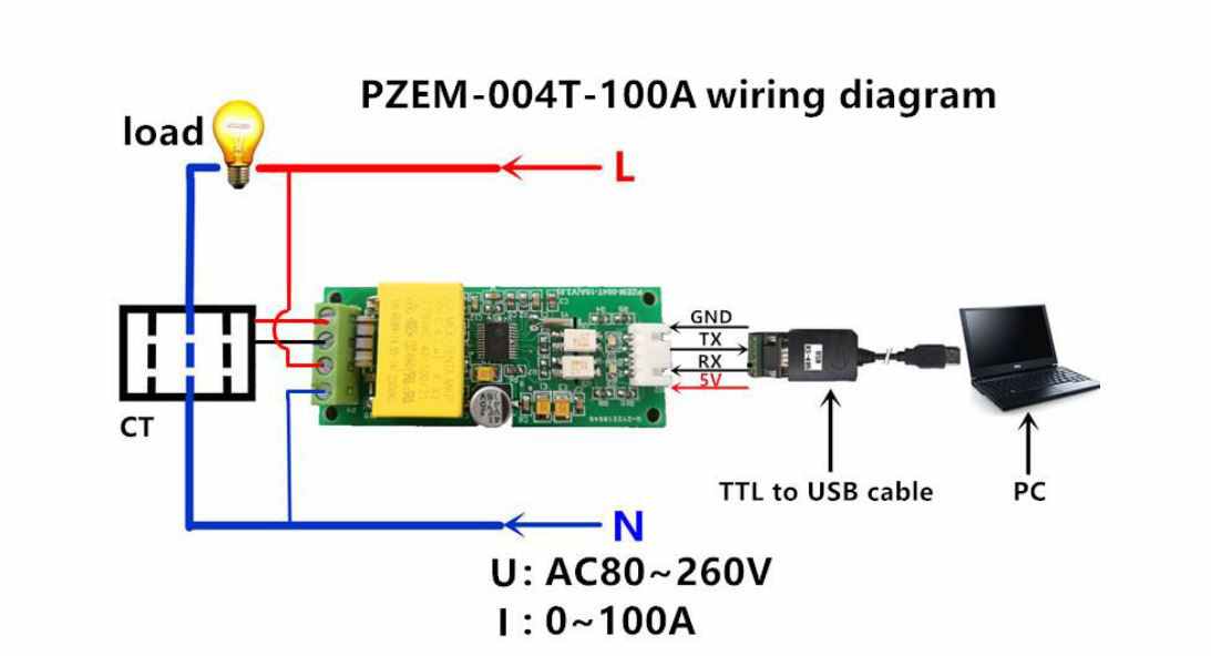
If you connect PZEM-004yt V3 – 10A a disaster happens !!!!
why no one has reported this problem?
https://ae02.alicdn.com/kf/A9598c69b311c41c0a5ed8d04ef7744e9m.jpg
Thanks for reporting the big mistake in the image, it was copied from the manufacturer’s website, so I was also unable to detect it.
This is a 100A version (look at the description/label in left top corner) so maybe other people ware mote watchful and they check if they have 10A or 100A version. Wiering diagrams are different in both devices.