IoT Based Distribution Transformer Monitoring System | PPT | Code | Report
The main objective of this project is to design and develop Transformer Monitoring System using Arduino and Real time IoT platform connected using GSM module.
Project Abstract
To maintain the reliability in grid operation it is important to monitor real time transformer health. We know the importance of transformers in electricity distribution and transmission. They are the main components and constitute the sizable portion of capital investment of the distribution grid. Real time transformer health monitoring systems help to replace the equipment before failure and continuity of the power will not be disturbed.
Why it’s important to develop IoT Based Transformer Monitoring System?
To understand this, we need to find the drawbacks of the conventional transformer monitoring system and the biggest problem in the electricity distribution grid.
- Most of the distribution transformer are remotely located in a rural area, where regular monitoring by human observation is difficult to perform due to insufficient manpower.
- Our existing monitoring systems are not supported for real-time operations. There are too many transformer failure cases detected every day.
- Not allowed for planning operation downtime.
- Conventional system Don’t have any internal fault testing [incipient fault monitoring]
To overcome the above drawbacks, we need a smart and reliable solution to monitor the distribution transformer parameter and send it to the IoT platforms in real time. It enables the grid operator to define the performance of the unit. It also provides valuable information about transformer health. IoT Based Transformer Monitoring System will allow the utilities to optimally run the transformer and keep this equipment in operation for a longer period.
The important parameter we need to monitor
- Transformer Temperature
- Oil Level
- Oil Quality
- Current level
- Voltage level
- Humidity
- KVA and Power Factor
- Incipient fault monitoring
Added Features
- Flux based interturn fault detection
- Overcurrent Protection alert and Protection
- Overvoltage protection alert and Protection
- Temperature Control [stage 1 :Fan on | Stage 2 : Disconnection]
- Oil Quality monitoring using optical sensor
- Kva and power factor alert
- Oil level monitoring using ultrasonic sensor
Keywords: Transformer health monitoring using IoT, Real Time, Arduino.
Reference Papers and Link
- Distribution transformer monitoring system using Internet of Things (IoT) [IEEE 2017]
- Design and Implementation Smart Transformer based on IoT [IEEE 2019]
- Transformer Health Monitoring System Using Internet of Thing [IEEE 2018]
- Fault analysis of oil-filled power transformers using spectroscopy techniques [IEEE 2017]
- A smart IoT based system for monitoring and controlling the sub-station equipment [ScienceDirect 2019]
- A New Leakage Flux Based Technique for Turn to Turn Fault Protection and Faulty Region Identification in Transformers [IEEE 2018]
[ Note: use 5th or 6th paper title to while submitting in college, this title looks heavy and new. Easily accepted by your project guide]
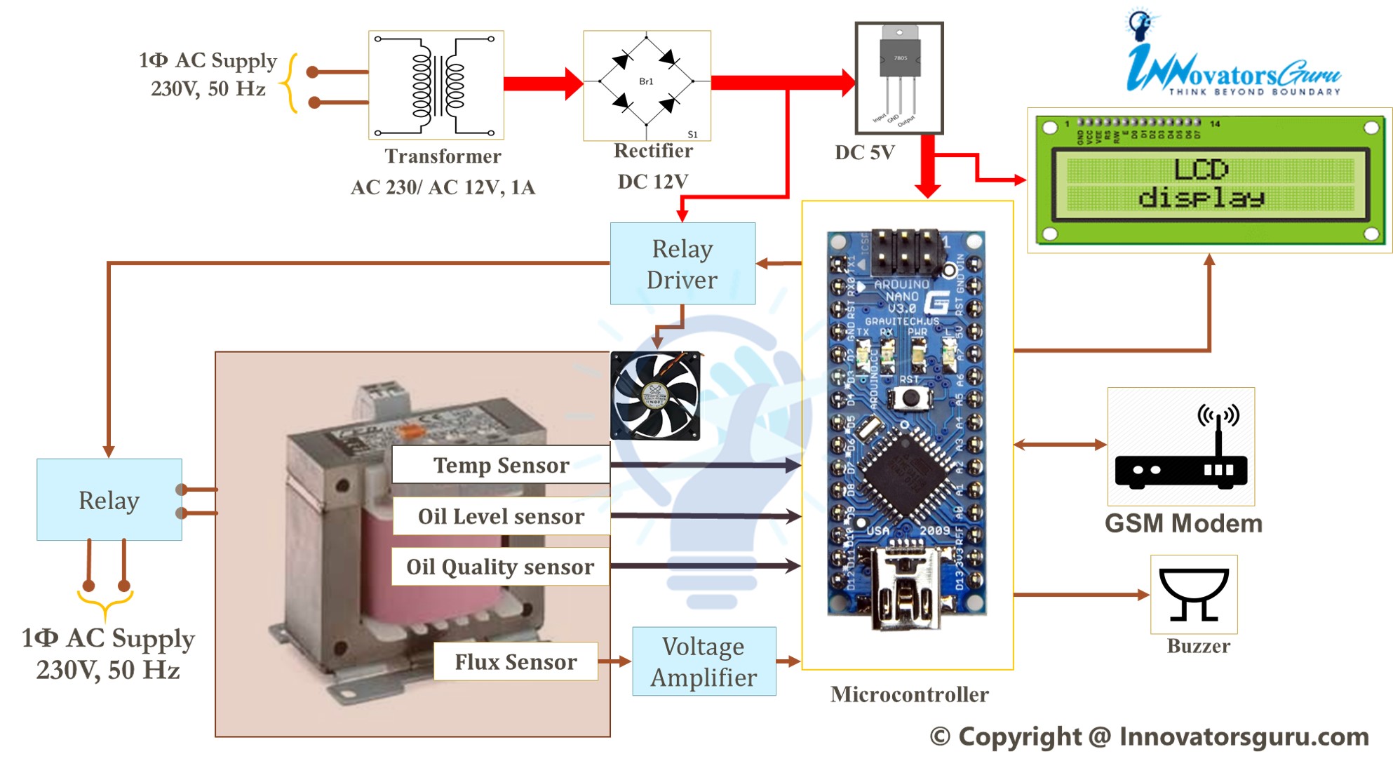
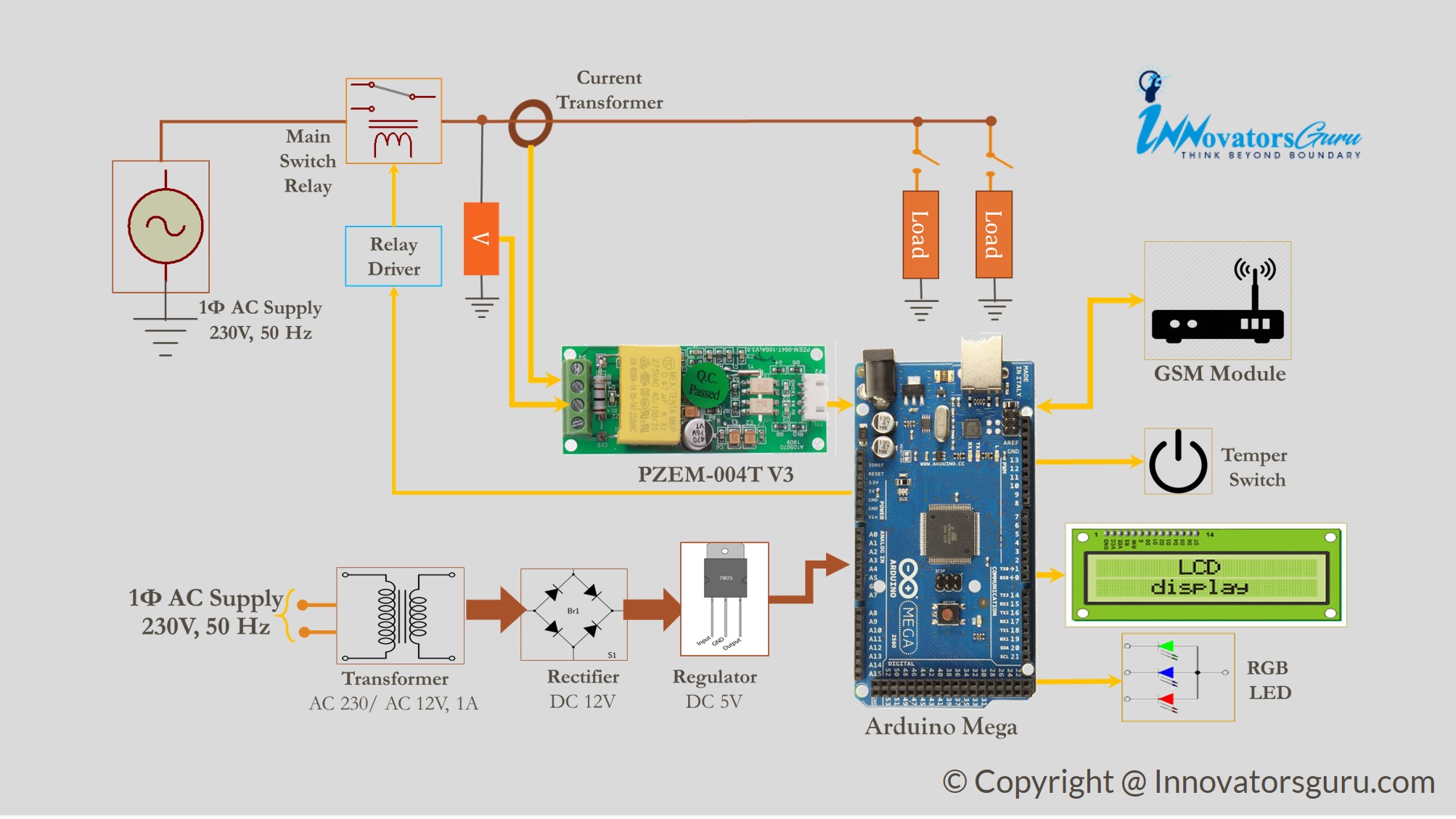
Block Diagram
Block diagram of IoT Based Transformer Monitoring System Using Arduino will represent the complete visual representation to understand the project concept.
Understand the Proposed System
The Proposed monitoring system based on IoT consists of three main systems:
- Parameter measurement subsystem
- Protection Subsystem
- Data reception subsystem.
Firstly, transformer electrical and physical parameters are measured by using the Parameter measurement subsystem. Electrical parameters consist of internal flux, voltage, current, KVA, Frequency and power factor and in physical parameter we include temperature, oil level, oil quality and humidity.
To measure the above parameter, we need different sensors and modules to interface with the Arduino microcontroller. A list of the components is provided in the next section.
In the protection subsystem, Arduino controls the operation of a fan and protection relay to protect the transformer in a faulty condition.
The current state and measured parameters are sent to the remote IoT server by using the data reception subsystem. We have two IoT platforms that are available to use for testing, the first is thingspeak and Ubidot stem.
By using the IoT and Arduino monitoring and protection algorithm, a smart self-protection system is designed for the transformer. Where, if any major fault (overvoltage, overvoltage, interturn, stage 2 temperature etc.) is detected in transformer monitoring system transformer is immediately shut down. If transformer is not serviced in low oil quality, low oil level, the system will send alert
Optional feature: The Protection system will separate loads based on priority in case of minor fault in transformer. Disconnect the less important load (workshops, residence etc ) and it will keep loads of high importance (hospitals, substations etc.). If the transformer available rating is unable to run loads of high importance, in this case system will separates all loads and stay in the no-load status where the monitoring system monitor its parameters by itself, if all major parameters of the transformer return to the normal level, the monitoring system automatically reconnect the loads in priority order.
Hardware component you need to design real time transformer health monitoring system using IoT

Arduino Nano
To process the measured value

GSM Module SIM800C
SIM800C supports GPRS class 12 with max. 85.6 kbps (downlink/uplink) speed which is enough bandwidth for our real time transformer health monitoring system using iot projects. SIM800C GSM module is the best choice for this project as we are planning to monitor remotely located distribution transformers. Wi-Fi module is most suitable for short-range where WIFI router is available.
Some key features of SIM800C Module
- Control via AT commands
- Easy to Use
- Low power consumption
- Easily Available
- Low Cost

LCD Module 16×2 or 20×4
To show the measured parameters we are using LCD module. the following parameter are show on lcd screen
- Voltage
- Current
- Power (Real time power)
- Energy consumption
- Power Factor
- Energy Bill

Relay Board
For Protection, controlling the on-off operation of transformers and disconnection from grid we need relay board.
Power Supply
To run the control board and sensor we need at least 5v 1.5A DC.
- Step down Transformer
- Rectifier
- filter capacitor
- Voltage regulator
ADVANTAGES
- Detect the faults in real time based on current, voltage, temperature, and internal flux.
- Increase system reliability and stability by the monitoring system.
- The system prevents faults and losses of the power supply which significantly benefits utility consumers
- Overcurrent and overtemperature are prevented using this technique.
Application
- Distribution transformer monitoring
- Smart Grid
- Power Transformer Monitoring
Arduino Code
Get the complete step by step Arduino project code. Project code is divided into multiple stages to understand its working and algorithm
- LCD Interfacing
- Testing Relay Board
- Temperature Measurement
- Humidity Measurement
- Oil quality Measurement
- flus sensor Interfacing
- AC power Measurement module Arduino interfacing and Display data on LCD
- Overvoltage Undervoltage Protection code
- Arduino and GMS module Interfacing
- Internet Testing
- Send Random Data to IoT dashboard [ubidot] [Thingspeak]
- Final Code with all features
This is the best final year project you can do for a diploma and Degree in electrical engineering. The complete project budget is less than seven thousand for hardware components. We tried to provide you with as much possible diy data. We get lots of student’s requirements on this project about its DIY guides, project report, ppt, Arduino code, abstract, circuit diagram and readymade hardware.
To complete this requirement of students, my team and I will make a complete project package for you. We spend hours of time and do multiple testing to create a complete project package. We’ve combined audio explanations and presentations, reports, Arduino code and videos to make it extremely simple to understand. Therefore, you’ll get the best of knowledge as well as a project!
sir how can i get code, circuit diagrams and report for this project
Intrested in that project kindly send me your number or email or any other channel of communication from which we can discuss further..
sir from where you got idea to make project on it?
This are most important problems in field.