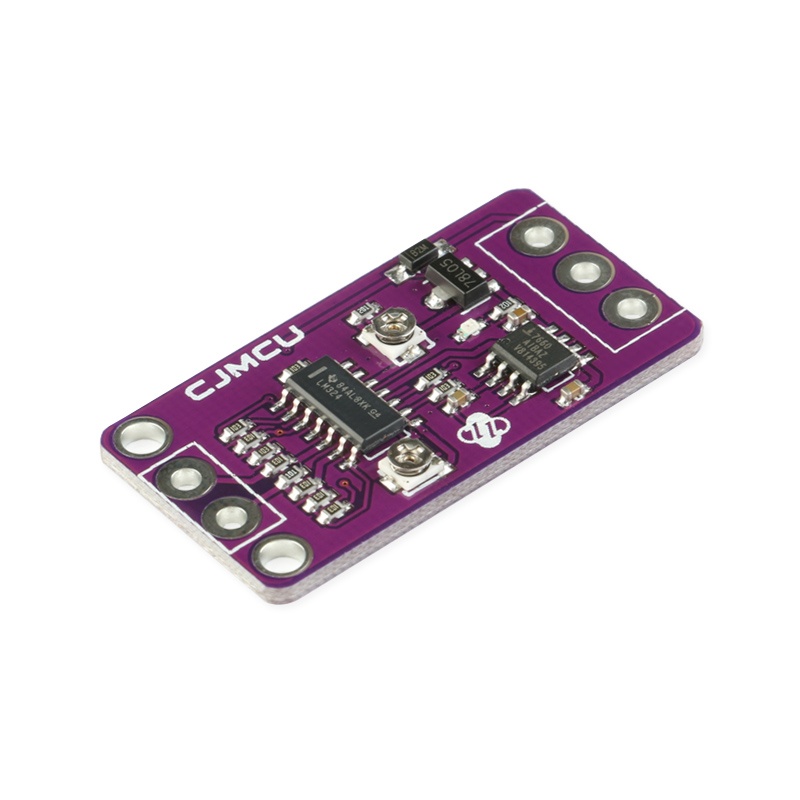
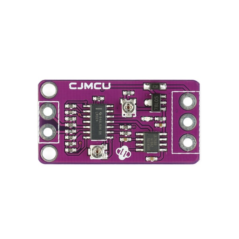
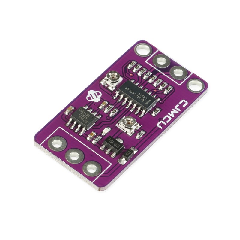
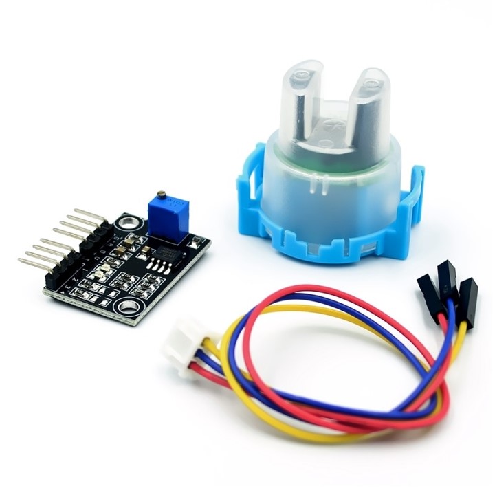
CJMCU-3247 | Current to Voltage Converter
Why 4-20 ma signal sensor is used in Industrial instrumentation?
In the process of circuit signal transmission in long cable, voltage drop and Electromagnetic interference are two major problems. Very long cables have resistance and that will cause a voltage drop. The voltage drop will degrade in signal accuracy. Current signal doesn’t have this problem as well as Current signals are immune to electromagnetic interference.
Why 4ma is used instead of 0ma and why 20ma max is used?
If sensor is faulty or broken wire, it can be easily identified. If the output is zero ma it will be difficult to identify whether it is a faulty signal or a good signal.For error detection this 4 ma scale is maintained. selection of 4mA range is depends on semiconductor. As semiconductor devices requires 3mA current to operate, standard had to be above 3mA.
20 ma is used as max because the human heart can withstand up to 30 ma of current only. For safety reason 20 ma chosen as maximum value. this is the main resion of Scaling of 4-20 ma.
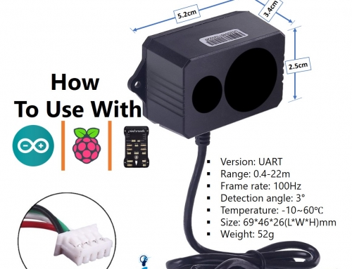
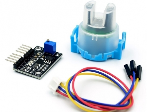
This Module is used to convert current signal 4-20ma to 0-10vdc voltage Output (adjustable 24V MAX).

CJMCU-3247 Specifications
- Supply voltage: 7 – 30 V DC
- Input current: 0/4mA – 20mA
- Output voltage: 0 – adjustable (24V MAX)
- Temperature drift: ±100ppm/°C
CJMCU-3247 Features:
- Wide supply voltage range,
- the output voltage to support multiple ranges
- Zero and range can be adjusted
- High stability, good linearity, industrial grade
- Current signal sampling resistor with high precision resistance,
- small temperature drift
CJMCU-3247 Application
- Industrial Automation
- TWO-WIRE, 4-20mA CURRENT LOOP TRANSMITTER
- INDUSTRIAL PROCESS CONTROL
- TEST SYSTEMS
Advantages of using 4-20 mA current Loop Sensor
- The 4-20 mA current loop is the dominant standard in many industries.
- It is the simplest option to connect and configure.
- It uses less wiring and connections than other signals, greatly reducing initial setup costs.
- Better for traveling long distances, as current does not degrade over long connections like voltage.
- It is less sensitive to background electrical noise.
- Since 4 mA is equal to 0% output, it is incredibly simple to detect a fault in the system.
Limitations of using 4-20 mA current Loop Sensor
- The currents can induce magnetic field and crosstalk to parallel lines. Thus you always should use a twisted wire and keep it distant from other communication lines.
- Current loops can only transmit one particular process signal.
- Multiple loops must be created in situations where there are numerous process variables that require transmission. Running so much wire could lead to problems with ground loops if independent loops are not properly isolated.
- These isolation requirements become exponentially more complicated as the number of loops increases.
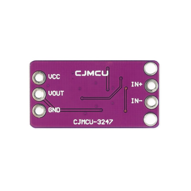
Instructions for use:
- Module according to the definition of wiring, power supply voltage 7-36V (if the output to 10V, the supply voltage must be greater than 12V)
- After power-up, the D2 indicator should be on, otherwise check the line connection. Board with reverse protection, reverse does not burn.
- When the current input is the minimum (0mA or 4mA), adjust the ZERO potentiometer so that the VOUT output is the minimum (0.0V or other voltage)
- When the current input is at maximum (20mA), adjust the SPAN potentiometer so that the VOUT output is the maximum (3.3V or 5V or 10V, the output can be as low as 2.5V when the input is 4-20ma)
Leave A Comment