Automatic Power Factor Control | APFC
Any inductive load that operates on alternating current requires apparent power, but apparent power is the addition of active power and reactive power. Active power is the power which is actually consumed by the load. Reactive power is the power demanded by the load and returned to the power source. The simplest way to specify
Power Factor
POWER FACTOR is the ratio between the useful (true) power whose unit is (KW) to the total (apparent) power is (KVA) consumed by A.C electrical equipment or inductive load. The power factor is a measure of how effectively electrical power is used to perform useful work. The ideal power factor is unity or one. If the power factor is less than one it means that excess power is required to perform or achieve the actual work.
Advantages of Power Factor Improvement:
Advantages which can be achieved by employing the proper power factor correction scheme are:
- Increase in efficiency due to Reduction of power consumption.
- Reduction in power consumption leads to a reduction in greenhouse gasses.
- Reduction of electricity bills.
- Availability of extra KVA from the same existing supply.
- Reduction of I²R losses in transformers and distribution equipment.
An idea to improve power factor
The basic idea For Power factor correction of inductive circuits we have to connect a capacitor in parallel with the device which has a low power factor. One of the traditional methods for power factor correction is static type compensation in which static type capacitors are used for power factor correction. However, in this case, care should be taken when applying power factor correction star/delta type control so that the capacitors should not be subjected to rapid on-off conditions. Otherwise, back-to-back capacitor bank switching is usually associated with large inrush current and it may damage the equipment connected to the system.
Components required-
- Auxiliary power Supply
- Microcontroller(AT-mega328P)
- LCD Display
- Capacitor Bank
- Potential transformer
- current transformer
Working of APFC with GSM
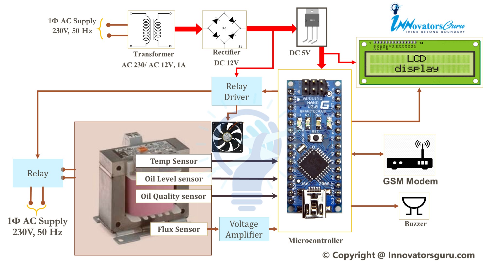
BLOCK DIAGRAM OF APFC

Working of APFC with GSM
A 220 Volts 50 Hz AC supply is given to transformer .Transformer steps down 230 Volts to 12 Volt AC. Output of transformer get converted to 5 Volts DC using IC 7805. The 5 Volts DC supply is given to microcontroller. Load voltage and load current are sensed by CT/PT. Such sensed Voltage and Current samples are given to the microcontroller and then microcontroller inbuilt comparator act as Zero Crossing Detector and determine power factor and output displayed on 16X2 LCD display. For given load if power factor is less than desired power factor capacitor bank 1 is switched on. After switching on bank l 27 desired power factor is not achieved, capacitor bank 2 is switched by using microcontroller to get desired power factor (> 0.95).
Capacitor Bank Calculation For APFC Panel
Features:
Ø High Performance, Low Power Atmel®AVR® 8-Bit Microcontroller Family Ø
Advanced RISC Architecture
- 131 Powerful Instructions – Most Single Clock Cycle Execution
- 32 x 8 General Purpose Working Registers
- Fully Static Operation
- Up to 20 MIPS Throughput at 20MHz
Ø Peripheral Features
- Two 8-bit Timer/Counters with Separate Prescaler and Compare Mode
- One 16-bit Timer/Counter with Separate Prescaler, Compare Mode, andCapture Mode
- Real Time Counter with Separate Oscillator
- Six PWM Channels
- 6-channel 10-bit ADC in PDIP Package
Ø Special Microcontroller Features
- Power-on Reset and Programmable Brown-out Detection
- Internal Calibrated Oscillator
- External and Internal Interrupt Sources 32
- Six Sleep Modes: Idle, ADC Noise Reduction, Power-save, Power-down, Standby, and Extended Standby
Ø Operating Voltage:
- 1.8 – 5.5V
Ø Temperature Range:- 40 0C to 850C
Advantages of using automatic power factor using GSM
Increase in efficiency due to Reduction of power consumption.
- Reduction in power consumption leads to a reduction in greenhouse gasses.
- Reduction of electricity bills.
- Availability of extra KVA from the same existing supply.
- Reduction of I²R losses in transformers and distribution equipment.
Disadvantages of APFC using Capacitor
- They have a short service life ranging from 8 to 10 years
- They are easily damaged if the voltage exceeds the rated value
- Once the capacitors are damaged, their repair is uneconomical
Conclusion –
This project provided one of the techniques used to overcome power losses due to low power factor associated with common household and small industrial units. To add value to the regular product (APFC), proposed GSM based APFC.
FUTURE SCOPE :
1) Prototype designed GSM system can be used for large rating of APFC system.
2) Introduction of Reactor in APFC panel has advantages as:-
- Reduces harmonic content in the network which further reduces disturbances in the telecommunication network, misbehavior in control equipment and relay protections, measuring errors in the metering system • Reduces network losses
- Reduces equipment overloading & stress on insulation
- Reduces cost, unplanned outages and increases power availability

![IoT Based Distribution Transformer Monitoring System Using Arduino | PPT | Code | Report [ 2020 ]](https://innovatorsguru.com/wp-content/uploads/2020/02/IoT-based-transformer-health-monitoring-system-500x383.jpg)
Mem please give me all details please…….