Capacitor Bank Calculation For APFC Panel
Welcome to this introductory part on capacitor bank calculation for an APFC panel. When I first started working on the calculation of capacitor bank I have struggled for many hours to figure out what was going on in this Capacitor bank calculation. Therefore, I have decided to write this tutorial for the ones who are new to these topic.
In this tutorial, we will discuss the calculation for capacitor bank in a simple way.
There are two methods for calculation of capacitor bank –
-
Simple Table Method for Capacitor bank calculation
-
Classical Capacitor bank Calculation Method
Let us take a example of 3Phase induction motor
1.Simple Table Method for capacitor bank calculation –
Motor Input = 5kW
From Table, Multiplier to improve Power factor from 0.7 to 0.96 is 0.692
Required Capacitor kVAR to improve P.F from 0.7 to 0.96
Required Capacitor kVAR = kW x Table Multiplier of 0.7 and 0.96
= 5kW x 0.692
= 3.46 kVAR
And Rating of Capacitors connected in each Phase
3.46/3 = 1.15 kVAR
2. Classical capacitor bank Calculation Method
Motor input = P = 5 kW, Voltage- 400V
Original Power factor= Cosθ1 = 0.7
Final Power factor = Cosθ2 = 0.96
θ1 = Cos-1 (0.7) = 0.7953; Tan θ1 = Tan (0.7953) = 1.0200
θ2 = Cos-1 (0.96) = 0.2837; Tan θ2 = Tan (0.2837) = 0.2915
Required Capacitor kVAR to improve Power factor from 0.7 to 0.96
Required Capacitor kVAR = P (Tan θ1 – Tan θ2)
= 5kW (1.0200 – 0.2915)
= 3.46 kVAR
And Rating of Capacitors connected in each Phase
3.46/3 = 1.15 kVAR
These are the main Formulas to Convert Capacitor kVAR into Farads and Vice Versa
C = kVAR / (2 π f V2) in microfarad
C = 3.46/ (2 π* 50*4002) in microfarad
C= 6.88* 10^-8 microfarad

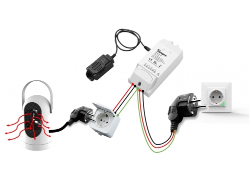
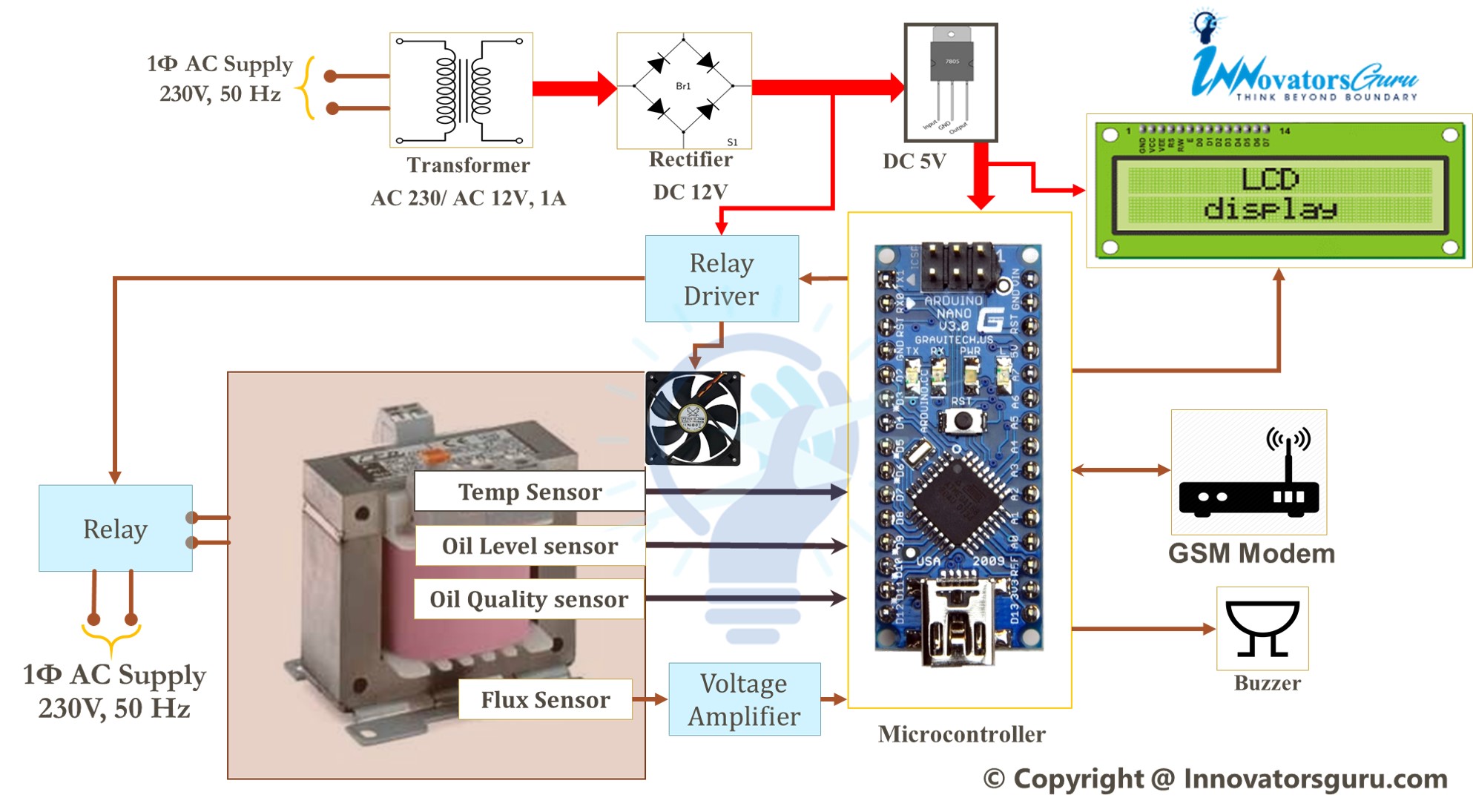
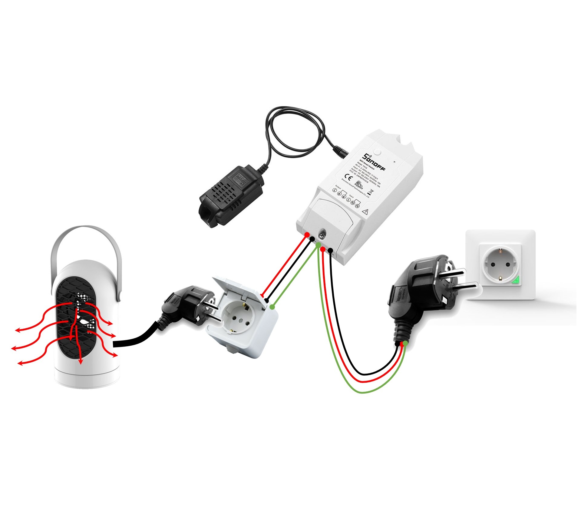
![IoT Based Distribution Transformer Monitoring System Using Arduino | PPT | Code | Report [ 2020 ]](https://innovatorsguru.com/wp-content/uploads/2020/02/IoT-based-transformer-health-monitoring-system-500x383.jpg)
Leave A Comment