AC Power Measurement using Arduino
Measuring AC power using Arduino microcontroller and Instrument Transformer. This article gives you a software and hardware solution concerning the Atmeaga328P microcontroller and the Instrument transformer power measurement module for measuring AC power. We also provide hardware and Arduino Program for AC Power Measurement.
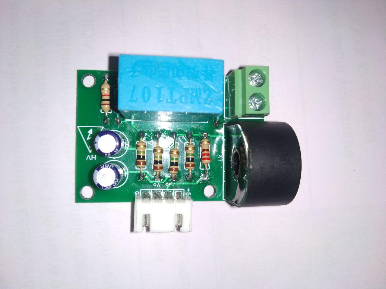
To ensure more accurate AC Power Measurement using Arduino, we designed cost effective DIY AC wattmeter using ZMCT103C current transformer and ZMPT107 Voltage Transformer. This DIY AC wattmeter is designed for the effective measurement of
- AC voltage
- AC Current
- Active Power
- Apparent Power
- Power Factor.
This DIY AC wattmeter module is used for single-phase power monitoring up to 1000V AC voltage and 100A current applications. You can easily interface this module to any microcontroller like Arduino, STM32, PIC, AVR etc.
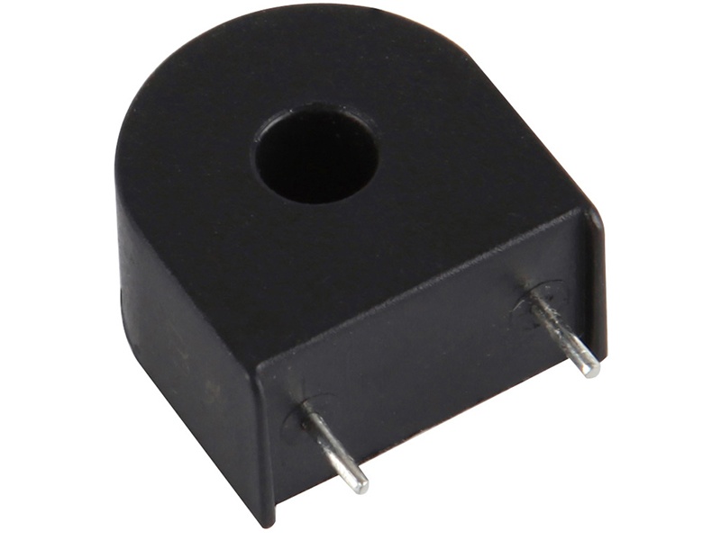
ZMCT103C high precision PCB mount micro current transformer converts a high primary current into a lower secondary current. This module makes it easy to monitor AC mains current up to 5 Amps. For Higher current measurement you can replace ZMCT103C with PBT terminal and connect any wired current transformer up to 100A.
There is a need for accurate and economical methods of voltage and current measurement using Arduino boards.
Power measurement. The main objective of this project is Power Measurement to reduce peak on generation by providing customers with their instantaneous power consumption. The aim of providing such data to the user is to encourage them to shift their load during non-peak hours and reduce their power usage and electricity bill.
ATMEGA328P has an embedded 10-bit ADC for current and voltage measurement, GPIO for LCD management, and a lot of other peripherals for communication, tamper detection, keyboard, and power disconnection. Powerful architecture of the STM32™ microcontroller allows sampling at 1 Msps. The high sampling rate makes it possible to use methods for ADC resolution enhancement.
Why you need AC Power Measurement using Arduino
Electrical AC power measurement is at the heart of most applications in the electrical Infrastructure for
- Electrical power supply management,
- Demand Side management
- Supply side management
- Electricity usage control (sub-metering),
- Portable power quality analysis.
- Condition monitoring, and
For AC power measurement using Arduino, you have two unique solutions:
-
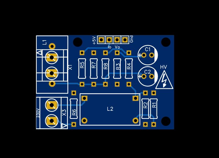
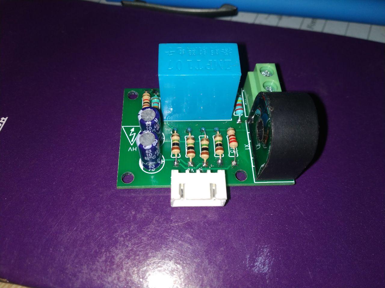
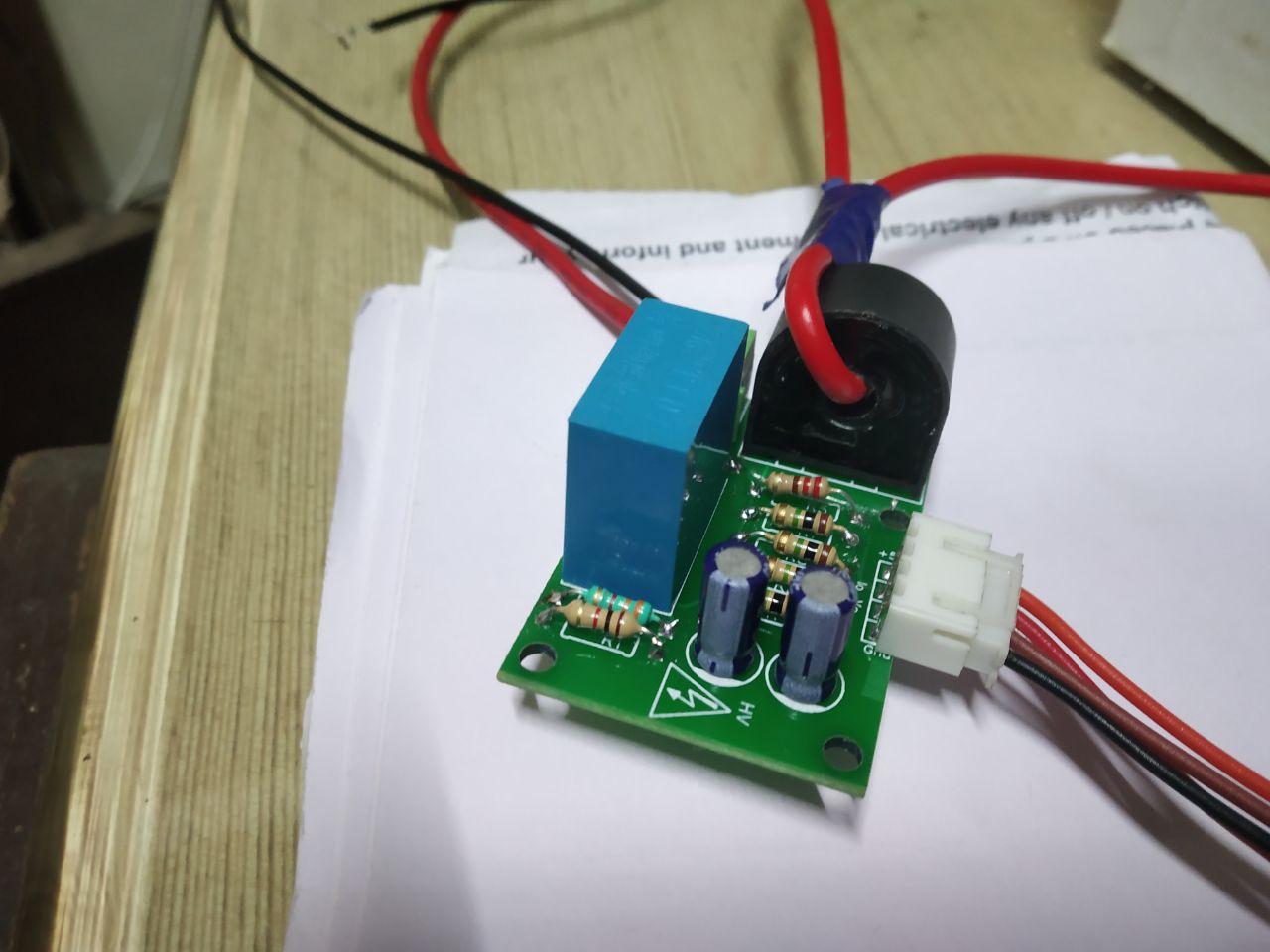
DIY AC power measurement Board
-
Ready to use AC power measurement Board
DIY AC Power Measurement Board
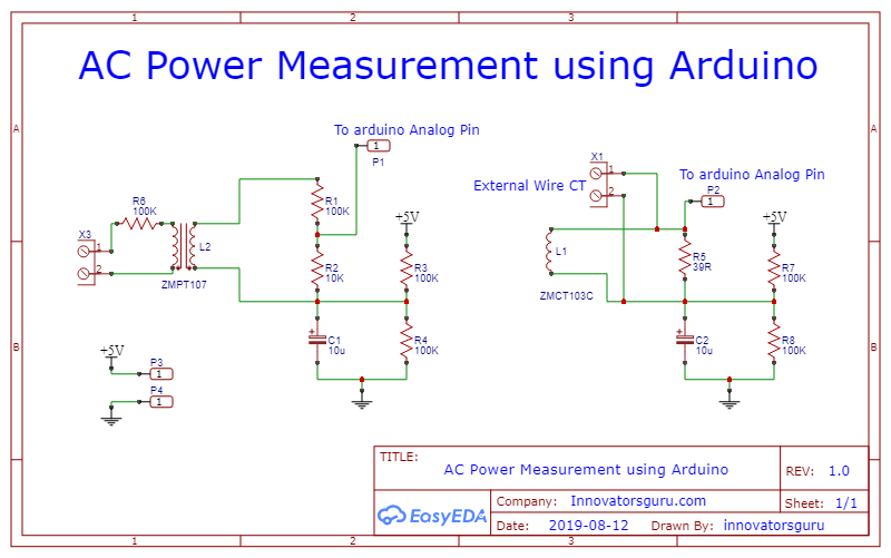
Note: Voltage transformer used in this circuit has 1:1 voltage ratio. Because of this risk of high voltage while handling this circuit, this project is not suggested for beginners.
The major parts of this measurement board are Instrument Transformer. Here we need AC voltage measurement as well as AC current measurement to get the power.
- Voltage Transformer
- Current Transformer
- Burden Resistor
For resistor divider calculations, visit. ZMPT101B | Best Small Size AC Voltage Sensor (innovatorsguru.com)
Current Transformer
A current transformer is an “instrument transformer” that provides current in its secondary, which is accurately proportional to the current flowing in its primary.
Key specifications of Current Transformer
-
- Accuracy: measurement accuracy directly affects the efficiency of an overall system. Power Measurement requires current sensors with accuracy much better than 1%.
- Drift: The drift of a sensor is related to the sustainability of reading over time.
- Linearity: The linearity of the sensor refers to the stability of its characteristics within the full operating mode.
- Phase shift: The phase shift should be as low as possible.
- Price: The price of the sensors is important when accurate current sensors are required for power measurement
For AC current measurement using Arduino we are using ZMCT103C Current Transformer. Get more details about ZMCT103C current transformer.
Voltage Transformer
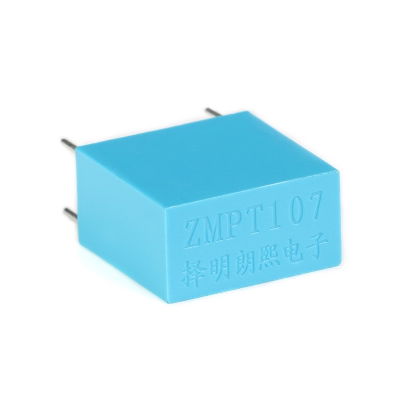
For AC voltage measurement using Arduino we are using ZMPT107 voltage Transformer. Get more details about ZMPT107 voltage transformer.


![IoT Based Distribution Transformer Monitoring System Using Arduino | PPT | Code | Report [ 2020 ]](https://innovatorsguru.com/wp-content/uploads/2020/02/IoT-based-transformer-health-monitoring-system-500x383.jpg)
Hello, I saw your ac power measurement using Arduino..
Do you have projects measuring ac power factor using pic16f877a..
Sorry, Right now we don’t have code for pic microcontroller.
Hey I clicked the link for the however it said the page could not be found.
In which link you get this problem, please mention.
Hi, how accurately does this project measure
1. ac voltage,
2. current (mostly in milliamps range),
3. power,
4. pf
my project requires very accurate measurement for the above parameters. Can your project do it accurately for any load(linear and non-linear)? Thanks
Hi, how accuracy of measurements
1. ac voltage, +-1V
2. current (mostly in milliamps range), +- 0.1A
3. power, +-2W
4. pf +-0.1
Good day.
I am interfacing the CT CR8450 with Arduino and am using EmonLib in the code for interfacing it but at the serial monitor there is a lot of difference in the clamp meter and the sensor value. I have tried the many other codes for this but the issue is same. Can you helps guide me in the code how I can get accurate values from the CT. Thanks
Thanks for the guide. I’m trying to wrap my head around how I can expand this to measure power on multiple circuits, first directly on the Arduino, and then moving on to a 16-1 multiplexer like HC4067 after I’ve prototyped it. Since they all would share ground, would I have to keep doubling R5, R7, and R8 and halving C2 each time I add a copy?
Yes, you must replicate the circuit to get multiple voltages, I tested it for three phase 4wire connections with Arduino Mega.
16-1 multiplexer I am not sure about it.
Hi, Can I directly interface this board to MC which is operating at 3.3v?
yes, you can, need to optimize resistance value to get good results.
how to get the software for this project?
The specification for the ZMPT107 indicates a burden resistor around 50 ohms to avoid saturation and phase shift. Why is yours so high at 110k ?
Where is the Arduino code
Arduino code is added, modify it as per your requirements.
What you call a voltage transformer, the ZMPT1007, is actually a current transformer but for a very low current: 2 mA.
on the primary side the current is determined by the series resistor(s), the same current also flows secondary through the load resistor, the burden.
A current transformer should never be used without a burden because the voltage would then rise much too high.
It appears that you have used different R1 & R2 values in your PCB than those shown in your schematic. Is that correct please?
It looks like R1=1K and R2=3.3K in the pictures?
Thanks & Regards
Dave