PZEM-004T
*Important Notification:
Manufacturer of PZEM-004T updated version to replace the old version. The old version has been sold out and no produce anymore.
* *The new version of PZEM-004T has higher precision, faster refresh speed,More parameter and more stability in communication than the old version.
Check the latest Version of PZEM-004T
PZEM-004T is the best for the purpose of the DIY project, where we need to measure the voltage, current and power using Arduino/ESP8266/Raspberry Pi like opensource platform. In many electrical projects, engineer directly deals with measurements with few basic requirements like
- High galvanic isolation
- Parameter display
- Direct communication with computer
- Data acquisition and storage with subsequent viewing or copying to the computer.
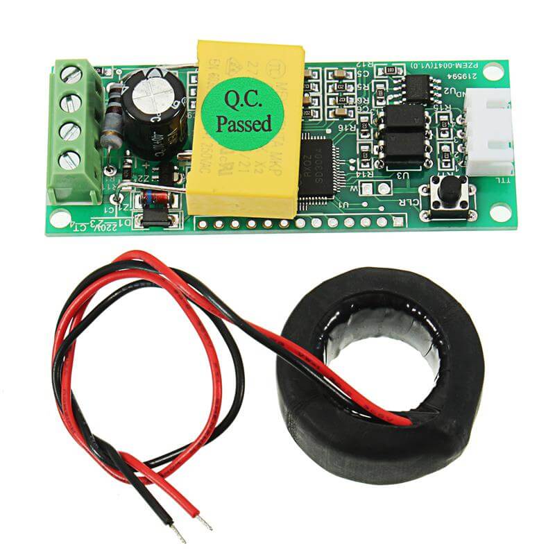
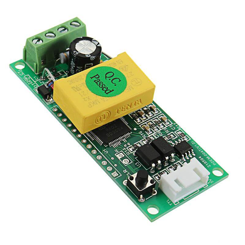
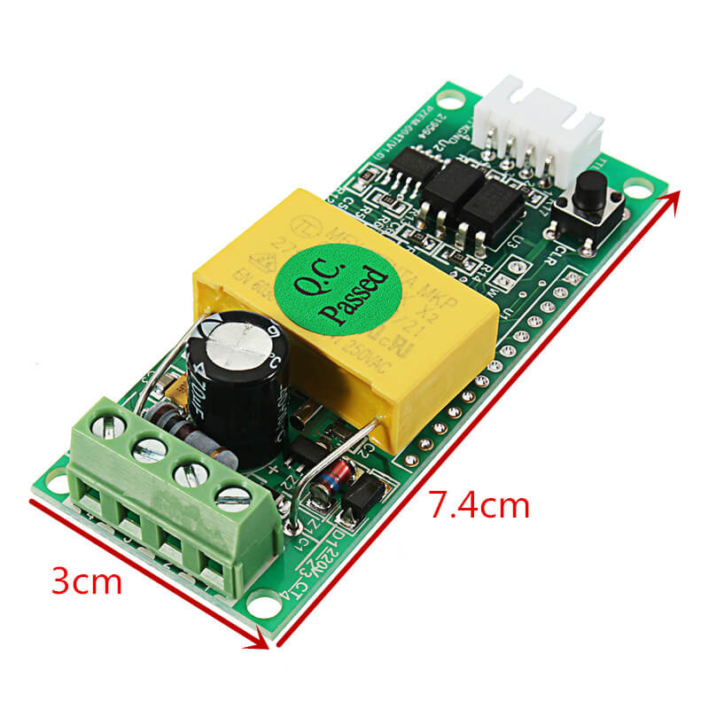
This module serve all these basic requirements of measurement PZEM-004T as a separate board. The physical dimensions of the PZEM-004T board is 3.1×7.4 cm, The pzem-004t module is bundled with 33mm diameter current transformer coil.
The main part of the PZEM-004T module is the SD3004 chip from the SDIC Microelectronics Co., Ltd. In addition, the board having the EEPROM from Atmel(now microchip) 24C02C which is a 2K bit Serial Electrically Erasable PROM with a voltage range of 4.5V to 5.5V. with More than 1 Million Erase/Write Cycles and 200+ Years Data Retention. Two optocouplers PC817, providing galvanic isolation of the serial interface.
Module Features
- Measuring consumed electricity
- Serial interface UART with a speed of 9600
- Supply voltage 5V
- The possibility of connecting LCD or LED displays
Function
1. Electrical parameter measurement function such as voltage, current, connected load and total consuption.
2. The power button clear function.
3. Power-down data storage function (cumulative power down before saving).
4. The serial communication function (comes with TTL serial interface, via various terminals communicate with the adapter plate, read, and set the parameters).
Display Format
1. Power: measurement range 0 ~ 22kW
- 0 ~ 10kW within the display format of 0.000 to 9.999;
- Within 10 ~ 22kW display format 10.00 ~ 22.00.
2. Power: measurement range 0 ~ 9999kWh
- 0 ~ 10kWh within the display format of 0.000 to 9.999;
- 10 ~ 100kWh within the display format of 10.00 to 99.99;
- 100 ~ 1000kWh within the display format of 100.0 to 999.9;
- 1000 ~ 9999kWh and above the display format from 1000 to 9999.
3. Voltage: Test Range 80 ~ 260VAC
- Display Format 110.0 ~ 220.0.
4. Current: measurement range 0 ~ 100A
- Display Format 00.00 to 99.99.
Button
A built-in button on the panel, used to make an electricity clear function.
Electricity clear method: Press ZERO key five seconds, then release the button!
Press again to clear the key, the data is cleared and exit charge cleared, cleared so far completed.
Serial Communication
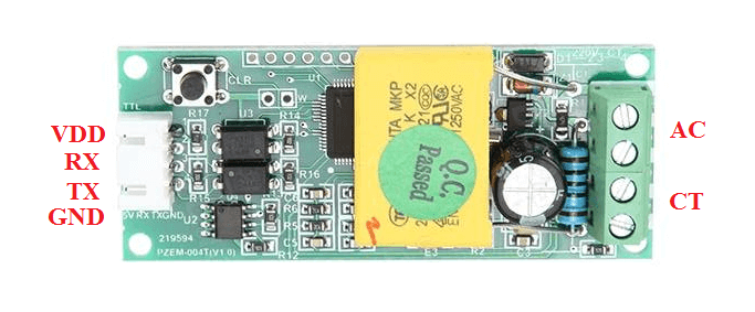
The module is equipped with a TTL serial data communication interface via the serial port can be read and set the relevant parameters; but if you want a device with a USB or RS232 (such as computers) to communicate, then you need to be equipped with different TTL adapter hardware board (USB communication needs with TTL to USB adapter plate; RS232 communication needs with TTL to RS232 adapter plate), the adapter plate of the specific connection details can be found in FIG.
Considerations
1. This module is suitable for indoor, not outdoor use.
2. the applied load should not exceed the rated power.
3. The wiring can not be wrong.
Download links
[ratemypost]


I am really delighted to read this web site posts which carries plenty of useful
facts, thanks for providing such data.
There is noticeably a bundle to know about this. I assume you made certain nice points in features also.
Most of what you articulate happens to be supprisingly legitimate and that makes me wonder the reason why I had not looked at this with this light previously. Your piece truly did turn the light on for me personally as far as this particular issue goes. Nevertheless at this time there is actually one factor I am not really too cozy with so while I make an effort to reconcile that with the core idea of the point, allow me observe what all the rest of the visitors have to say.Nicely done.
i used pzem-004t v2.0 with arduino uno at starting it work fine but after same time it stop working in serial monitor it only showing 0.00v. plz help me out.
First, check 1)is your Arduino working correctly for a blink program,
2)Check wiring: from arduino to PZEM-004t, and check with a multimeter that 230v appears at voltage input of PZEM-004T.
3) If you are using software serial chang rx and tx pin
how does pzem004t read signals from current and voltage … so that it can be processed by microchip?
thanks,
pzem004t workes on a serial interface with an external microcontroller or microprocessor. For current measurement, it has its internal sampling resistor or external 100a CT. For voltage measurements, the voltage divider circuit is used for sampling voltage signals.
Hi, I wonder if this module is open source or not? I want to move the circuitry to my own custom board to save space. I didn’t found any information about the schematic.
Nb: I don’t have the module yet so I didn’t know what components are on board.
Thanks
Its internal circuit diagram in not available. Its chinese product made by Peacefair.
Is the max voltage 260V hard limit? I need to read in N. American “240VAC”. The actual peak-to-peak is momentarily at 339V across both L1 and l2 legs of the split-phase system we have. The “240V” is RMS. Will the PZEM-004T work in this scenario?
260V is RMS voltage limit, VP = VRMS × √2
Thanks. Good info!
Also, would the PZEM-004T be able to read power in *both* directions? That is, power watts expressed in either positive and negative values in near real-time?
I’d like to create a home energy meter with live graphs & historical tables for solar power — all recorded in a time-series database. This solar power can flow both into and out of the house depending on the rate of energy production vs home usage at any given time so power can be positive or negative as well. When its negative, the solar power is feeding back into the grid with its surplus energy.
I think its possible, not tested for bidirectional power monitoring ,
But while testing I notice one thing, If the current transformer wire are reversed then Power factor value is negative.
Does not work with PZEM-004T V3.0
Its tested no V3 module.
Hi is it possible to re calibrate the PZEM to use a 80 amp or 60 amp clamp transformer rather than the 100 amp transformer? I purchased a couple of the PZEM’s and would like to use some clamp transformers I already have. I noticed in the datasheet there is a calibration option is that able to recognize that there is a differently rated transformer or is there a setting I can adjust in the device to accommodate this change?
I never tried it. But as per datasheet its possible.
Olá ! Esse módulo faz a medição de fator de potência assim como as Potências Ativa e reativa?
hello! Does this module measure power factor as well as active and reactive powers?
– Yes
Please can you share the Arduino code I’m facing problem with the reset part of the code