AC Power Control using Triac

The TRIAC (triode for alternating current) is an ideal power electronics switch to use for switching applications because it can control the flow of current over both positive and negative half cycle of alternating waveform. It’s also having advantage of low cost over back-to-back thyristor circuit, To control current up to 4A, voltage up to 600V and low inrush I recommended Triac, above that back-to-back thyristor can work fine.
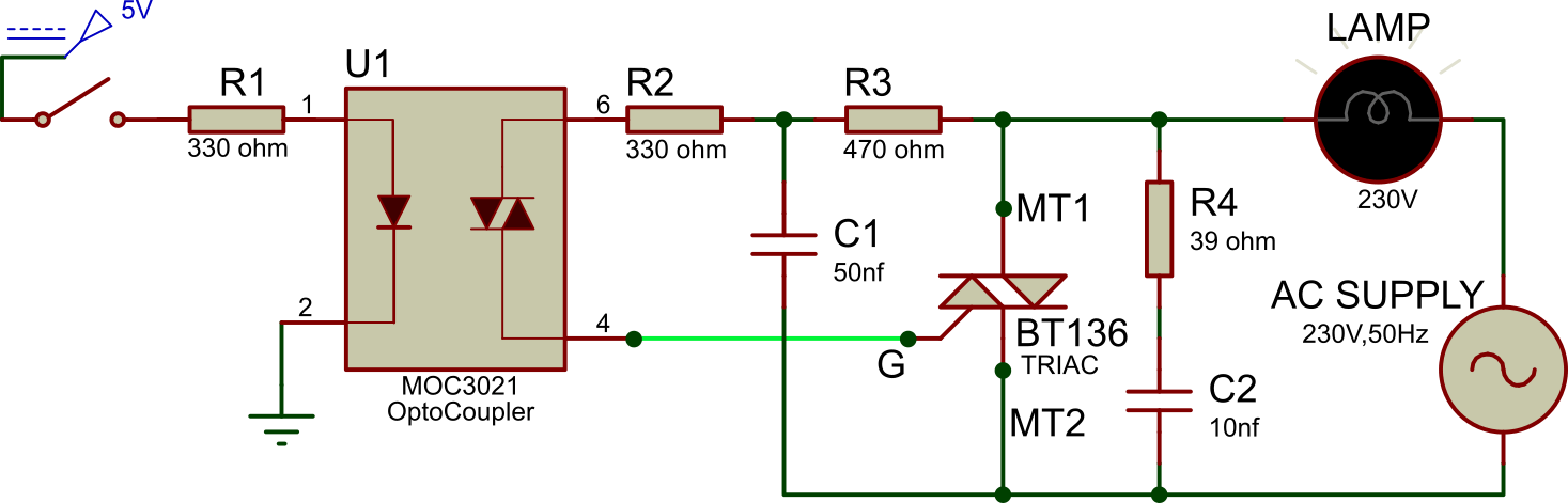
Controlling high voltage devices using optically isolated power electronics device give advantages of voltage control. This simple TRAIC circuit BT136 and Opto-coupler MOC3021 can able to control high voltage devices from microcontroller. For example, arduino to control 230/220v bulb or any device which runs on high voltage. This circuit can also work for dimming and speed controlling application using PWM signal from arduino.
As the TRIAC having bidirectional valve, this circuit used for AC and DC applications.
Circuit Diagram
Bill of Materials |
||||
|
S.No |
Reference |
Value |
Part |
Quantity |
|
1 |
R1 | 330 Ohms | Resistor ¼ watt |
1 |
|
2 |
R2 | 360 Ohms | Resistor 1/2 watt |
1 |
|
3 |
R3 | 470 Ohms | Resistor 1/2 watt | 1 |
| 4 | R4 | 39 Ohms | Resistor 1/2 watt |
1 |
|
5 |
C1 | 50nf/0.05uf,250/400V | Polyester capacitor | 1 |
|
6 |
C2 | 10nf/0.01uf, 250/400V | Polyester capacitor |
1 |
| 7 | U1 | MOC3021/3031/3051 | Optocoupler IC |
1 |
|
8 |
U2 | 6 PIN IC Socket | – | 1 |
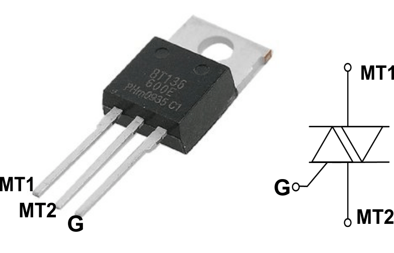
| 9 | TRIAC | BT136 | Triac |
1 |
|
10 |
LAMP | 100W 230V lamp | Incandescent lamp |
1 |
|
11 |
PCB | 4 cm×10 cm | 1 | |
|
12 |
Flexible Wire | 1 | ||
| 13 | Soldering Iron |
1 |
||
|
14 |
Soldering metal wire |
1 |
||
|
15 |
J1 | PBT Connector | 2 Pin | 1 |
| 16 | J2 | Male Berg Strip Straight | 2 Pin header |
1 |
|
17 |
Lamp Holder | 1 | ||
Working of TRIAC CIRCUIT
During ON Condition :
When 5v/3.3V is applied from micro-controller to the opto-coupler MOC3021 devices comprise gallium arsenide infrared emitting diodes at pin 1 & 2. This diode emit infrared light and trigger the optically coupled light activated silicon bilateral switch at pin 6 & 4 that allows current to flow between them. This supply provides GATE current to the TRIAC gate (pin 3 of TRIAC) and TRIAC conducts the main current between pin MT1 and MT2.
During OFF Condition :
When 0V applies to between pin 1 & 2 of optocoupler, pin 6 & 4 act as opened switched and doesn’t allow any flow of current between them, as there is no GATE current to TRIAC, it stops conducting.
Application of TRIAC SWITCH
- Solenoid/valve controls
- Static power switches
- Temperature controls
- AC motor starters
- Lighting controls
- AC motor drives
- E.M. contactors
- Solid-state relays
Disadvantages of TRIAC
In normal failure mode of electromechanical relay act as an open switch, while all SSR(power electronics Switches) acts as short circuit. Which may lead to continuous supply to load at failure condition.

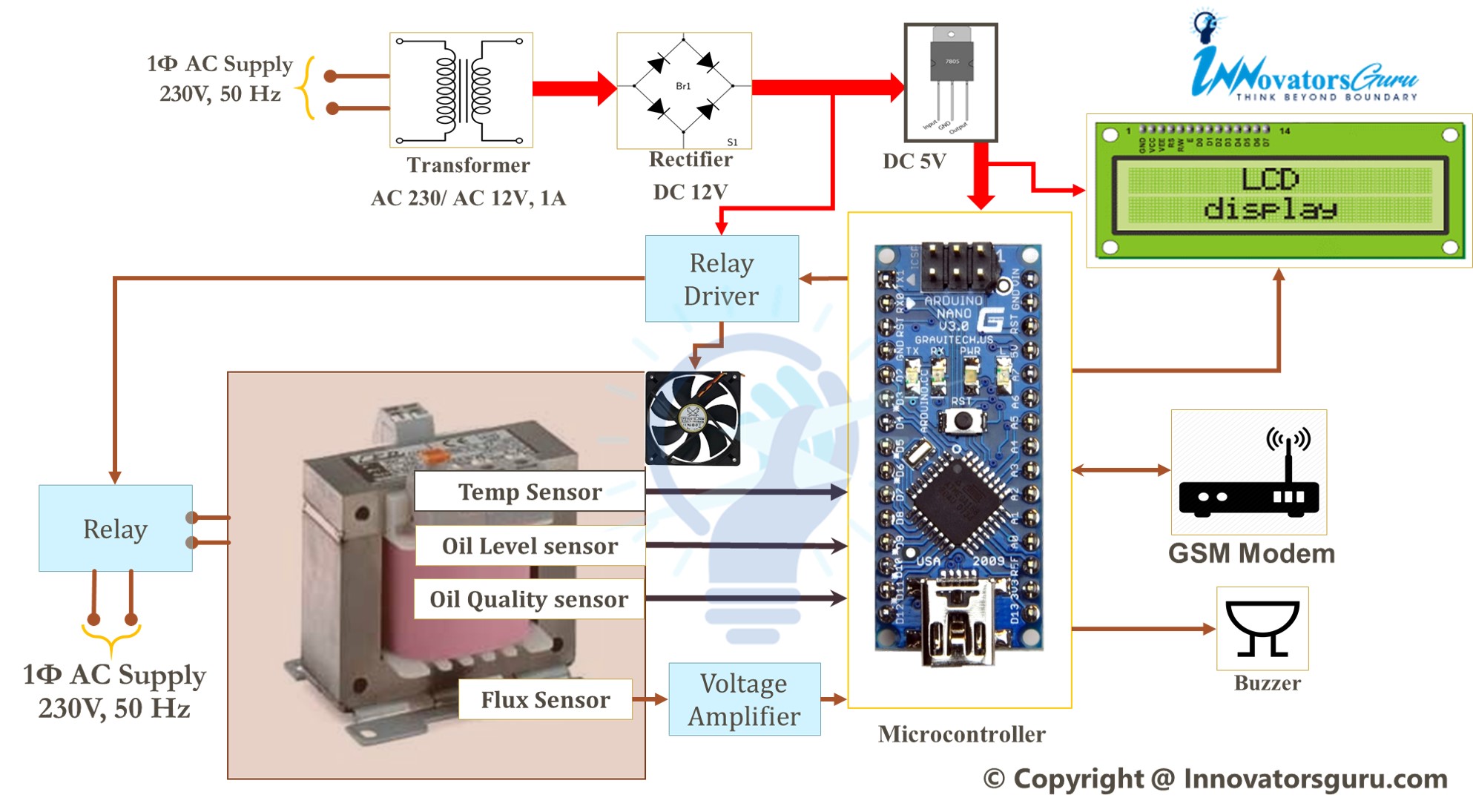
![IoT Based Distribution Transformer Monitoring System Using Arduino | PPT | Code | Report [ 2020 ]](https://innovatorsguru.com/wp-content/uploads/2020/02/IoT-based-transformer-health-monitoring-system-500x383.jpg)